Explaining Power Cable Pins: What You Need to Know
2024-08-01
The power cable I received has empty pins. Is it a defect?
The answer is No, it’s not a defect.
The pinout of the power cable is defined by the Intel Power Design Guide. For the 24-pin motherboard cable, the signal of 20th pin is reserved(No pin defined).
| Pin | Signal | Color | Pin | Signal | Color | |
|---|---|---|---|---|---|---|
| 1 | +3.3V DC | Orange | 13 | +3.3V DC [+3.3 V default sense] | Orange [Brown] | |
| 2 | +3.3V DC | Orange | 14 | -12V DC | Blue | |
| 3 | COM | Black | 15 | COM | Green | |
| 4 | +5V DC | Red | 16 | PS_ON# | Green | |
| 5 | COM | Black | 17 | COM | Black | |
| 6 | +5V DC | Red | 18 | COM | Black | |
| 7 | COM | Black | 19 | COM | Black | |
| 8 | PWR_OK | Gray | 20 | Reserved | NC | |
| 9 | +5VSB | Purple | 21 | +5V DC | Red | |
| 10 | +12V1 DC | Yellow | 22 | +5V DC | Red | |
| 11 | +12V1 DC | Yellow | 23 | +5V DC | Red | |
| 12 | +3.3V DC | Orange | 24 | COM | Black |
(Figure 1, Data source: Intel PSDG)
The power cable are all black on the market, which is different from Intel PSDG, would it be ok to use?
Answer: It’s OK. Intel PSDG defines the pin color for easy identification, users can tell the pin through table list above.
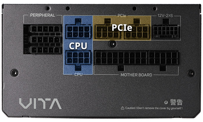
PCIe 6+2Pin for example, FSP has followed the same pin definitions of Intel CPU & PCIe on power module design, so they are not compatible. Be cautious inserting only to individual socket on power module when connecting cable to PSU.

The Intel standard PCIe and CPU pin definitions
PCIe pin definition:Only Pin 1 to 3 have power signal, actually functional, would it be enough to power up?
| Pin | Signal | Color | Pin | Signal | Color | |
|---|---|---|---|---|---|---|
| 1 | +12V3/V4 | Yellow | 5 | COM | Black | |
| 2 | +12V3/V4 | Yellow | 6 | Sence0 | Black | |
| 3 | +12V3/V4 | Yellow | 7 | COM | Black | |
| 4 | Sense1 | Black | 8 | COM | Black |
(Figure 2, data source: Intel PSDG)
According to Intel's definition, the maximum current of single pin is 7A. A PCIe 6+2Pin can supply up to 252W (7A x 3 x 12V), but 150W power consumption of each PCIe 6+2Pin is recommended, it’s because potential power loss might be caused by not properly inserted in real use.
The new graphics cards with high power consumption release these days have new pin definitions (excluded from what have mentioned above). The function of Sense Pin is to detect whether the graphic is powered up properly. The COM is the ground wire (GROUND).
CPU pin definition:
| Pin | Signal | Color | Pin | Signal | Color | |
|---|---|---|---|---|---|---|
| 1 | COM | Black | 5 | +12V2 DC | Yellow | |
| 2 | COM | Black | 6 | +12V2 DC | Yellow | |
| 3 | COM | Black | 7 | +12V2 DC | Yellow | |
| 4 | COM | Black | 8 | +12V2 DC | Yellow |
(Figure 3, Data source: Intel PSDG)
You may also be curious, why power modules share the same CPU/PCIe interface from some manufacturers on the market ?
The answer is very simple, because these manufacturers define the module their own interface setting on PSU unit side, and not follow the Intel PSDG. However, the pin settings of CPU connector on motherboards or the PCIe on graphics card shold always follow Intel's specifications (as shown in Figure 2 and Figure 3).
You might be interested
Learn More
Welcome to GITEX AFRICA 2025
Learn More
LN2-cooled RTX 5090D Paired with FSP MEGA TI Claims 7 World Records